Background
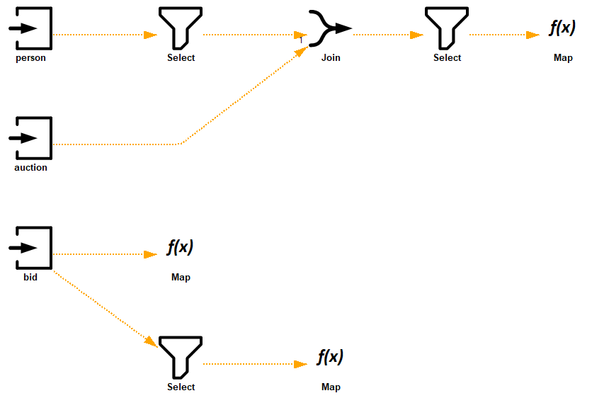
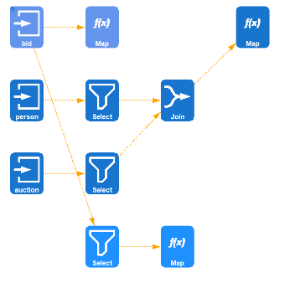
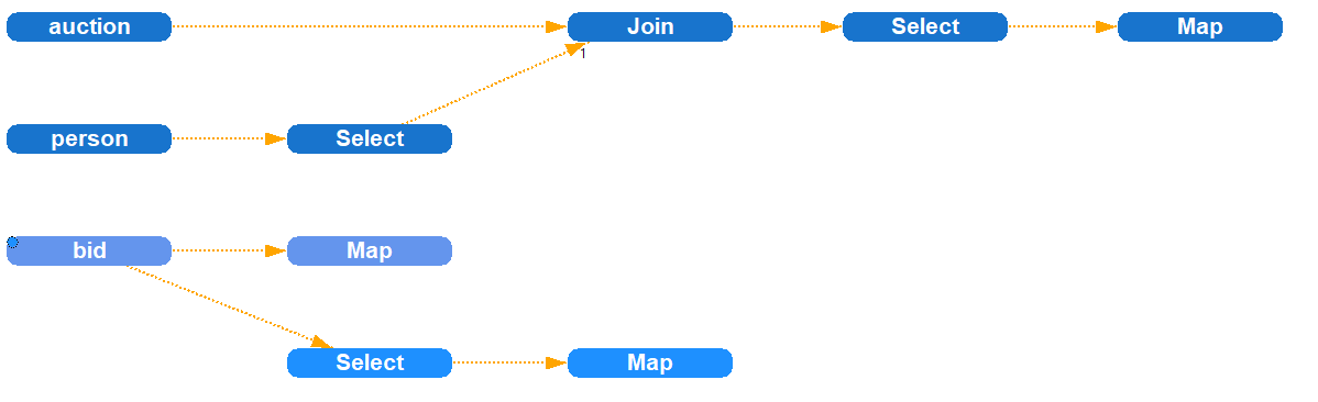
The visualization of the opertor graph in Odysseus Studio can be customized in order to change its style and appearance. The following pictures show some examples of different visualization styles provided by Odysseus.
The visualization framework provides several ways to control the appearance of the visualization which are described in the following sections.
Viewer configuration files
The way the nodes are drawn is defined in a special configuration file, the viewer configuration. It is an XML file that describes how to compose a node from different symbol elements. The schema of the file is defined in the SymbolSchema.xsd file. The following code snippet shows an example configuration file:
The Symbols element contains a list of definitions for node layouts. You can specifiy the layout individually for each type of physical operator by setting the nodeName attribute of the Symbol element to the respective class name. For each Symbol, you must specify its size and one ore more SymbolElement elements which describe the visual components to compose the node visualization. Some of these SymbolElement elements can additionally be configured using parameters that are specified as simple key value pairs. The following table gives you an overview of the available types of SymbolElement and the parameters they support.
| Component | Description | Supported parameters |
|---|---|---|
| TODO | ||
Besides the definitions for individual physical operators, the viewer configuration must specify the Default element which is applied to all operators that are not individually styled by a Symbol element. The structure of the Default element is similiar to the structure of the Symbol element.